The Magnetic Theater Overhaul (image heavy)
A several-week project to turn a living room into a dedicated home theater. Originally posted to avsforum in 2014.
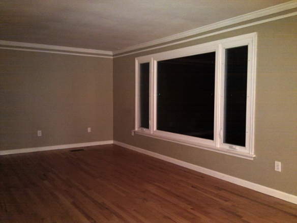
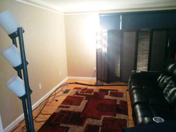
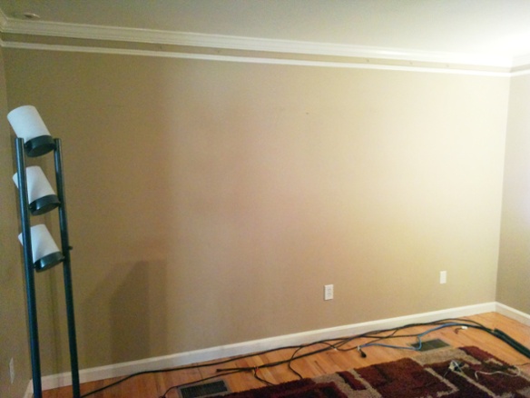
This isn’t a total room build, but it’s dedicated enough that the room isn’t usable for much else. The starting point was a living room with a big picture window, hardwood floors, and crown molding.
It also has large openings to adjacent rooms and stairs, and the only path to the upstairs bedrooms is through the back of the room. I wanted to do what I could while leaving the underlying room intact. I have another space where I might eventually do a more elaborate build, but I’m nowhere near ready to start on that.
BEFORE
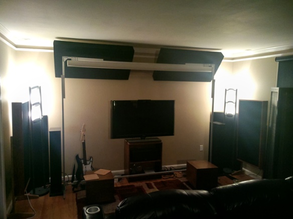
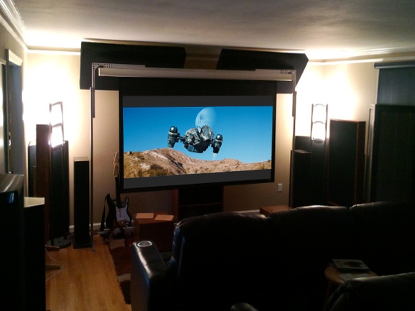
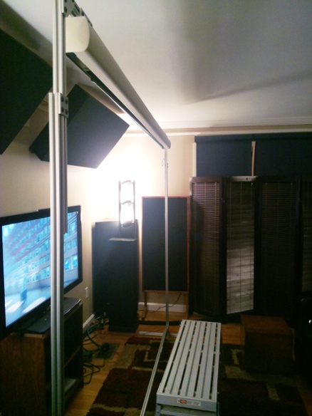
When I moved in a few years ago I basically just re-used the 7.1 setup from my old place with a few minor adjustments. I had an old 92”-diagonal 16:9 retractable screen which dropped down in front of a 46” LCD. Instead of ceiling-mounting the screen I built a floor stand for it, which was less trouble and let me lower it further for a better viewing angle. I also built a free-standing equipment rack in the back of the room. The side and rear speakers were just put on tall stands.
AFTER
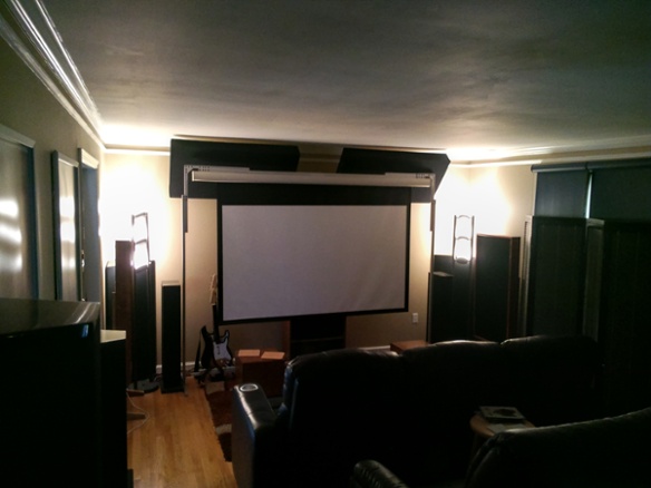
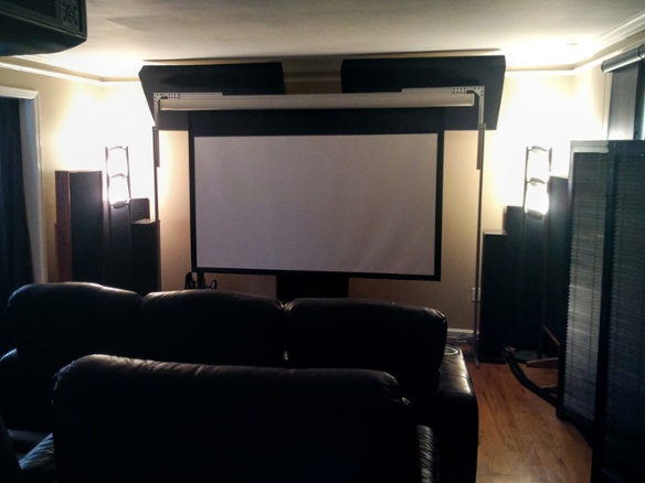
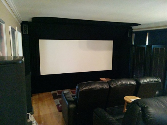
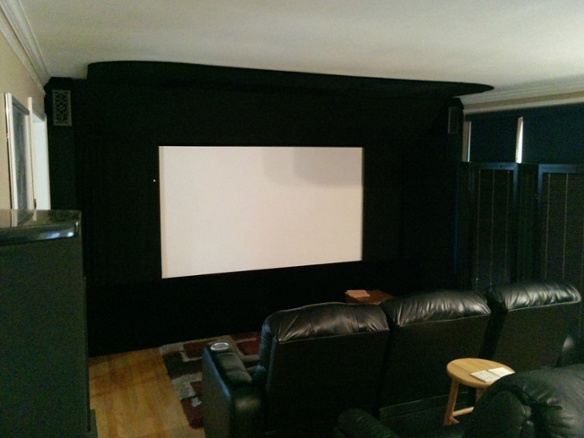
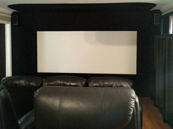
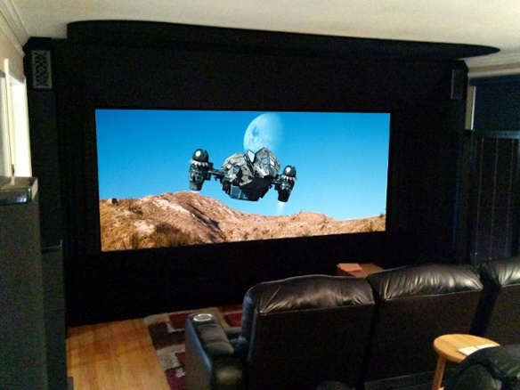
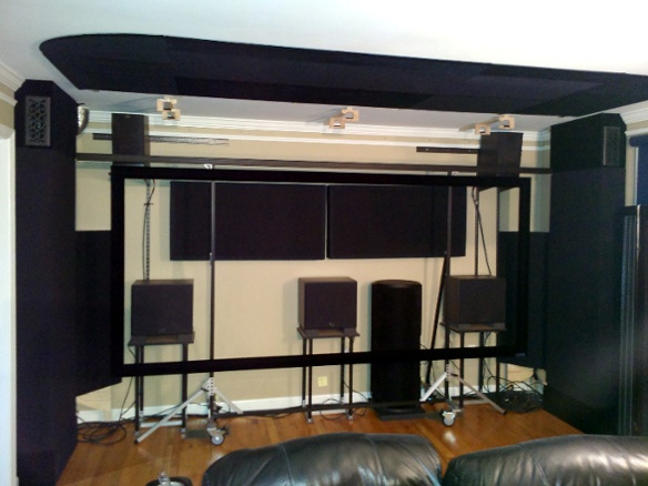
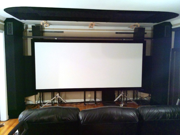
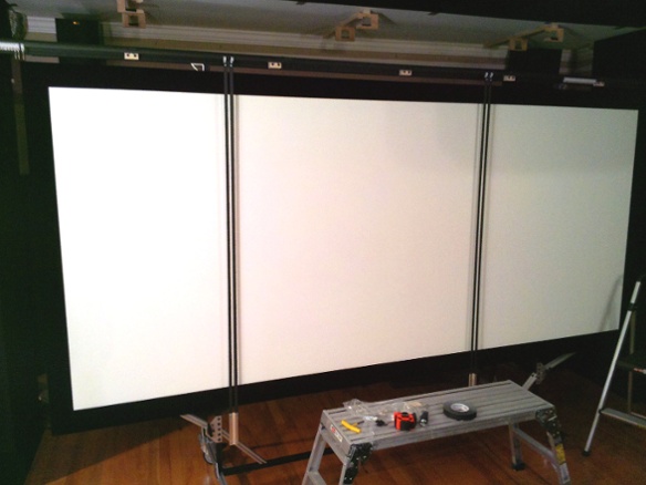
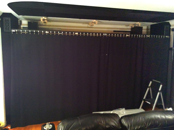
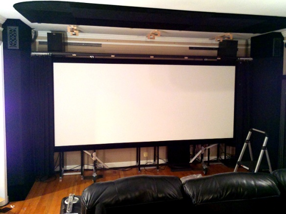
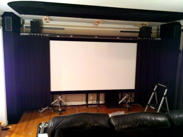
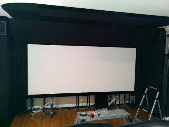
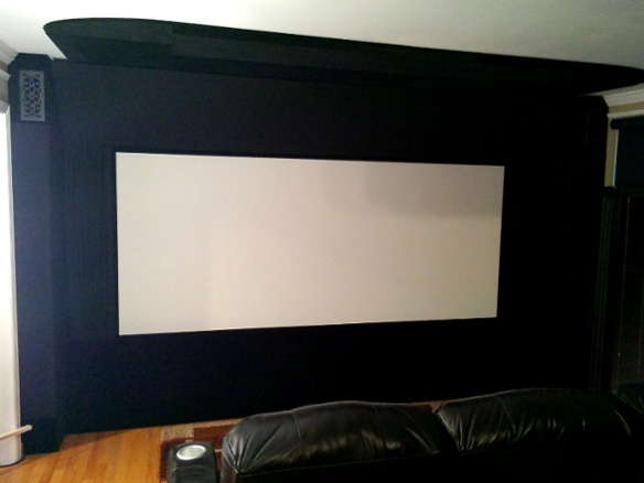
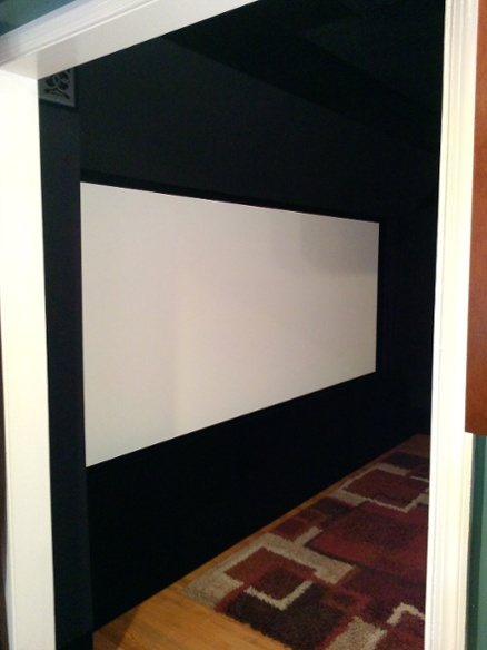
The old screen had a rechargable battery, which was originally much easier than wiring it in but after 12-13 years wasn’t holding much of a charge any more. It became more and more difficult to raise and lower it, so about a year ago I just started leaving it down all the time and using my old PT-AE2000U projector for everything including day-to-day TV. When it needed yet another bulb and the OEM prices had skyrocketed, I decided to upgrade the projector. That quickly led to a cascade of upgrades: 3D, 11.1 audio, new rack, and a much larger screen wall with fabric panels around a 120”-wide 2.35:1 AT screen. There are masking curtains that manually come in from the sides for 16:9 content.
I’d been wanting a larger screen for years, and so far this is doing the job. When watching a wide movie it is big, especially because my front row is only 8.5 feet away. Here’s a mockup showing the relative size of a 2.35:1 image on the two screens, but it doesn’t really do it justice.
Most of it was designed to be easily removed. For example the screen and curtains are on a wheeled stand that can be rolled away from the wall, giving access to the space behind the screen. Given a screwdriver and about an hour you could get the front of the room back to the original state with a handful of screw holes here and there.
I figured I’d call it the “magnetic theater” because there’s a lot of rare earth magnets holding things in place.
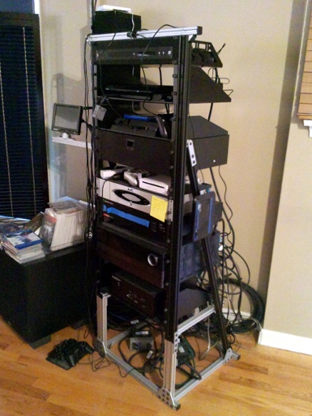
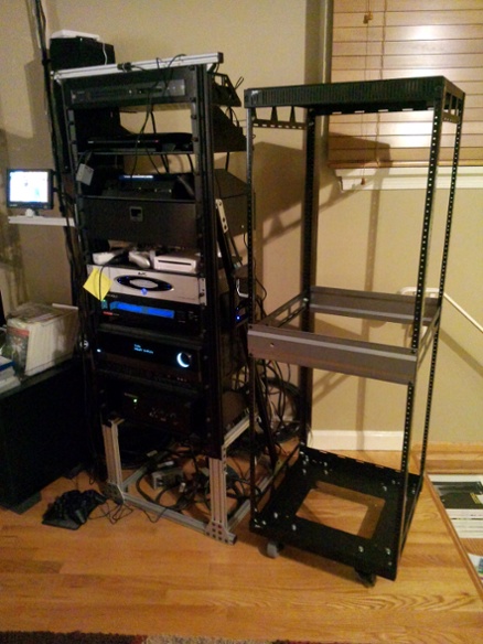
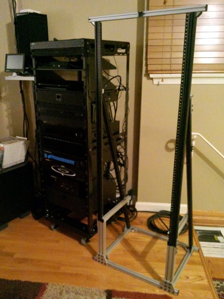
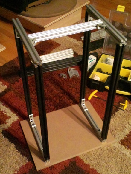
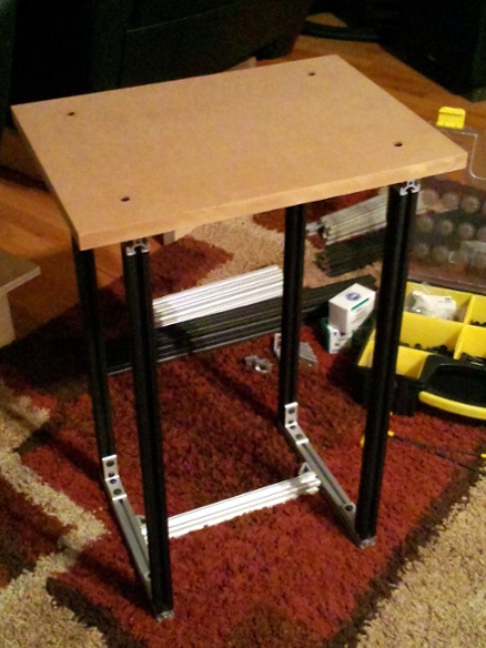
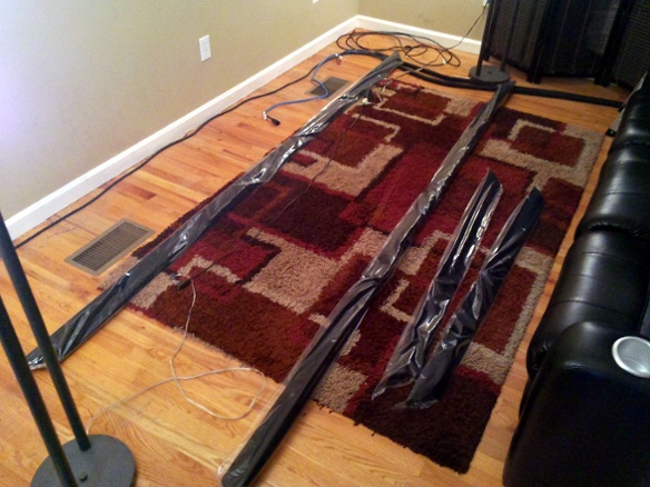
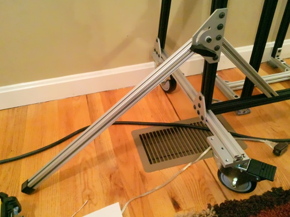
One of the first things that could be dealt with was the rack. At my old place I had a hole in the wall with rack rails bolted to the studs. The new place couldn’t accomodate an in-wall rack so I just threw together a stand to hold the rails, making it ouf of “80/20” T-slot aluminum framing. It wasn’t easily moved or rotated, but it mostly worked out.
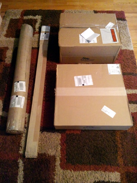
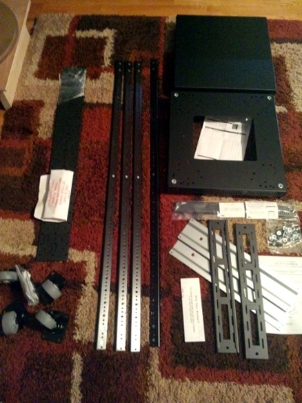
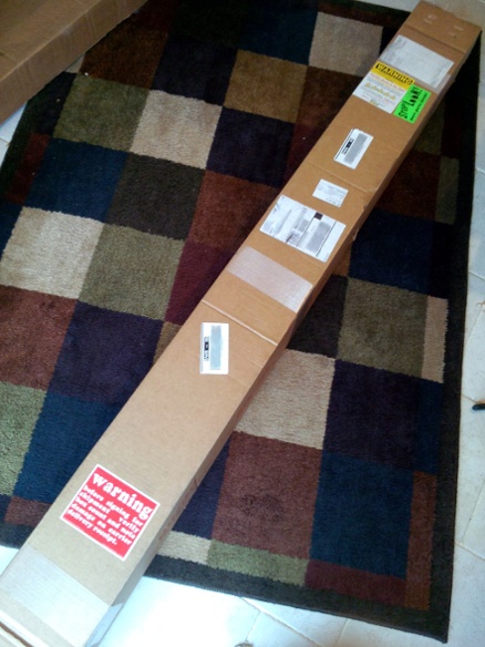
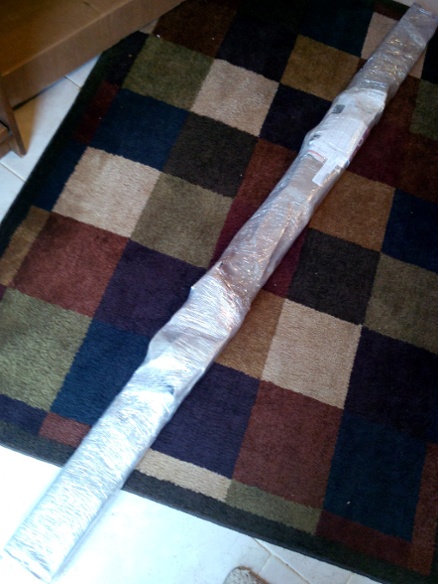
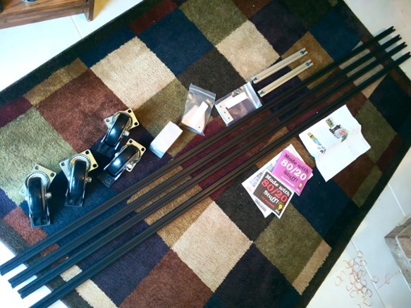
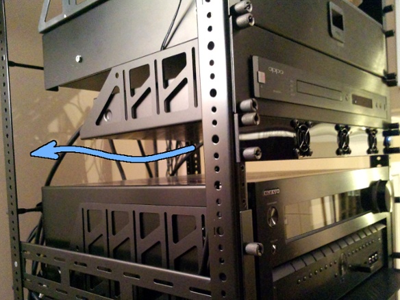
The big problem was that the rails didn’t have much space left, and I expected to need several more U for things like a larger receiver and a place to store/charge 3D glasses and such. I decided to replace it with a Slim-5 29U, which gets me a bit more room, rear rails for cable management, and is actually shorter because its rails go all the way to the bottom. I was tempted to step up to 37U but since I intended to use casters and it would still be out in the open, I was concerned that 37U might be too easy to tip over.
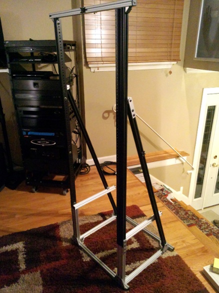
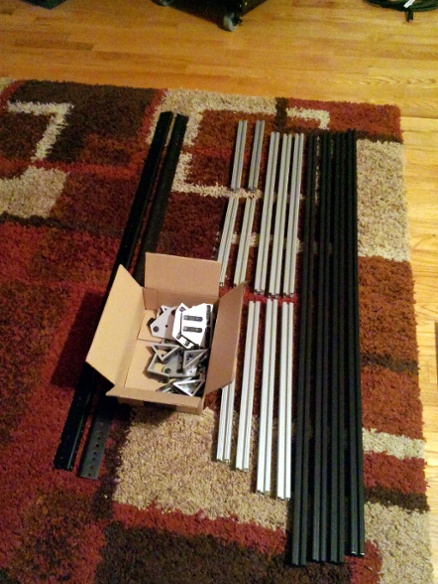
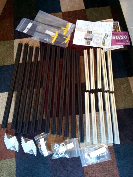
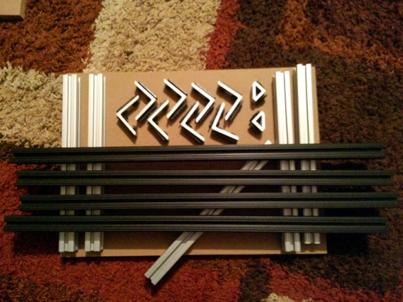
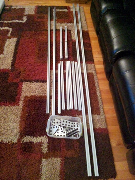
One of the nice things about using 80/20 is that once you don’t need something, it easily turns back into a stockpile of parts. I already had places for some of these parts to go in the new configuration.
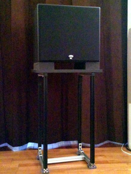
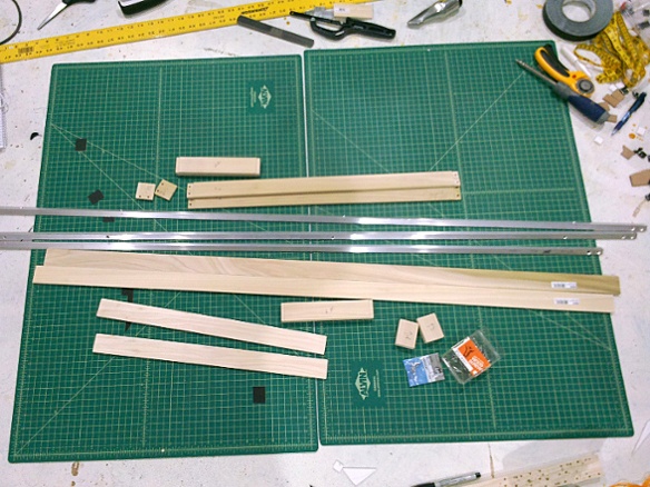
My old front speakers were DefTech BP2006 bipolar towers for left and right, and a much older DefTech C1 for the center. The new configuration moves the towers outward to be the LR-wide speakers, and for LCR I got three Klipsch KL-650-THX to go behind the screen. Which meant I needed stands for them. After looking at several options (there is a forum thread where someone listed some ideas) I decided to build some out of 80/20 and MDF.
The final stand is very light but also very rigid.
I put the speakers on Auralex MoPAD foam. If nothing else it was a reasonable way to get the extra 2” of height I needed since I took the easy route of using pre-cut 24” legs. I attached some non-skid pads to the bottom of the stands with double-stick tape, both to protect the floor and make sure the stands couldn’t vibrate out of position.
To black out any potential reflections behind the screen surface I wrapped the edge of the MDF with some black gaffer tape, and also stuck some tape on a couple spots where bright aluminum brackets were visible. Before final installation I also put some tape over the shiny Klipsch logo.
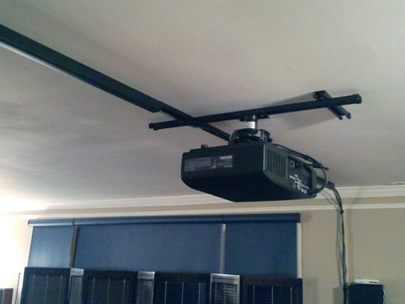
The new PT-AE8000U projector was the thing that started this upgrade-a-palooza, so by this point I had already mounted it in the same spot as the old AE2000U – which was a problem, because after doing a zooming test I found that it was a bit too close to reach the full width of the future 2.35:1 screen.
It had been attached directly to a joist for support, and the next closest joist was 24” away and right in the middle of the walkway. I have some tall friends including one who has hit his head on my foyer chandelier several times, so there’s no way I could just move the old mount 2’ back. The cable bridge I have on the walls and ceiling couldn’t easily move back to the next joist, either.
There’s also the issue that the AE2000U had a centered lens and the AE8000U has an offset lens. When using the old mount, the new projector’s lens was not centered. Lens shift could fix this for a single lens setting, but when doing constant-height via zooming I suspected that a lens shift (which is not adjusted by the lens memory) would interfere with the zoom. I knew from testing that a vertical shift would definitely cause problems for zooming.
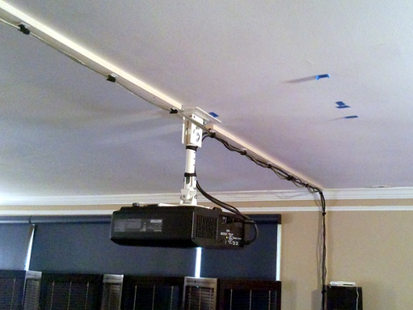
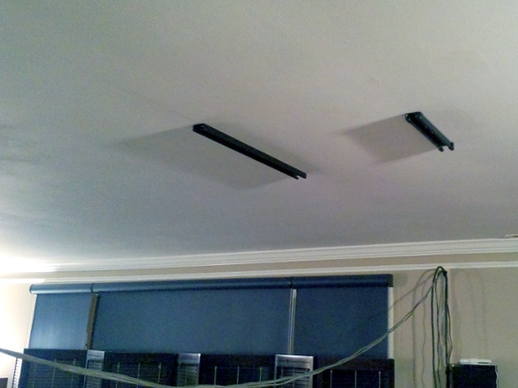
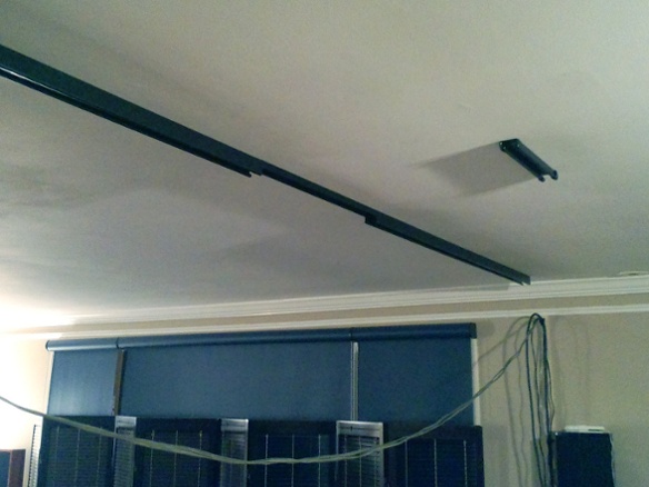
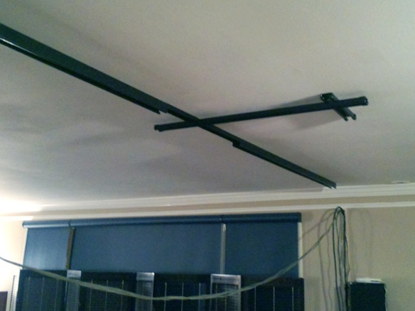
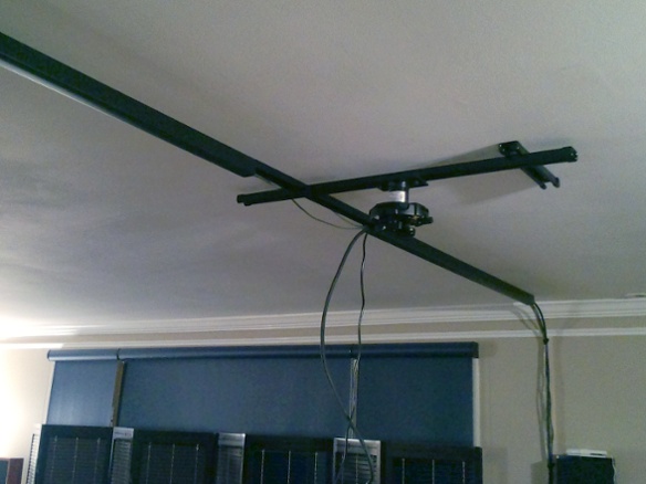
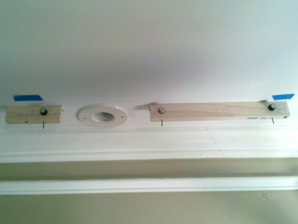
So I needed a new mounting system – something that could be off-center, and positioned between joists, and closer to the ceiling to give more headroom. I built a simple adjustable system using Unistrut. The strut channel was factory-painted and I also got some rubber end caps, so it’s at least less ugly than the channel they use at the office to hang conduit in the basement.
While I was at it, I also cleaned up the cable bridge by replacing the old board-and-velcro design with some strut channel that has a snap-in cover.
One piece of channel runs front-to-back between the joists and can be adjusted side-to-side to account for the offset lens.
I got a Peerless PRGUNV projector mount which is shallow and has some knobs for making tilt adjustments after everything is in place. They also make an adapter to attach a support column directly to strut channel. The column adapter can be moved back and forth on the channel to adjust the throw distance, and the height can be changed by swapping in a different column.
Right now I use a really short 3” column, but while this ensures nobody will bump their head it also puts the projector about 7” higher than it should be. I can’t use the lens shift to fix it, because that interacts with the zooming and results in either the 16:9 image being too high on the screen or the 2.35:1 image being too low. So for now I have to zero the shift and then tilt the projector downward to line up the top edge, which results in some keystoning as well as slight differences in focus from top to bottom.
It’s actually not that noticeable up close, but when you stand back you can definitely see the trapezoid shape at 16:9. Pulling out the masking curtains helps a lot with that by cutting a more vertical edge into the sides of the image. There’s not a lot of obvious distortion in the image itself, so once you make it hard to see that the sides are angled it’s hard to tell that anything weird is going on.
I’m sure I could reduce the keystoning by moving the projector back and/or down. I had my tallest regular visitor stand underneath it the other day and it looks like I could safely lower it another 3”, so that’s on the to-do list.
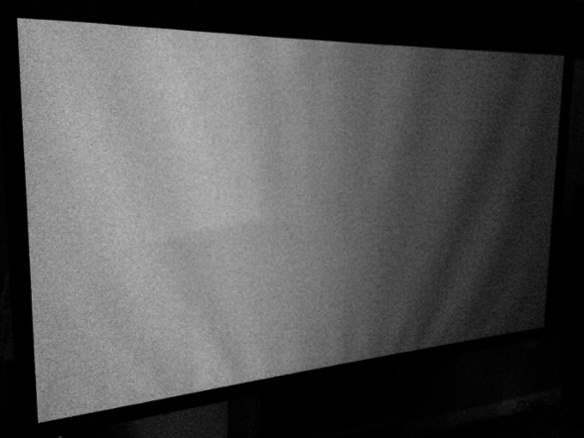
On the day the screen was to arrive, I finally started tearing down the old one. I took a last unflattering picture of the old untensioned retractable surface to show just how wavy it’s become after a dozen years. Back when I bought it, tensioned screens were way out of my price range. In a static shot it’s not that noticeable unless there’s straight lines going through the worst of the waves, but in a slow pan it can be really obvious.
The old stand just slid out on felt pads, and was quickly sent back to the 80/20 stockpile.
I also removed (i.e. scattered all over the house) the old front-wall speakers and traps, to get back to a clean slate.
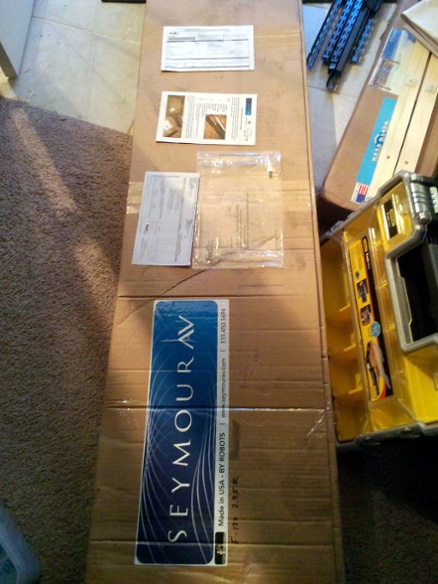
The new screen is a 120”-wide 2.35:1 SeymourAV CenterStage XD Premier. Since I won’t be painting the front wall I also got the black backing.
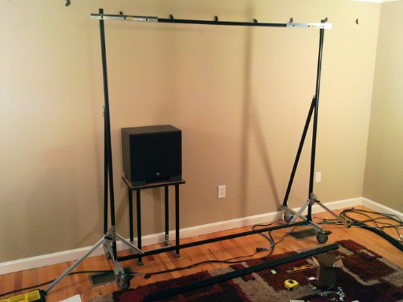
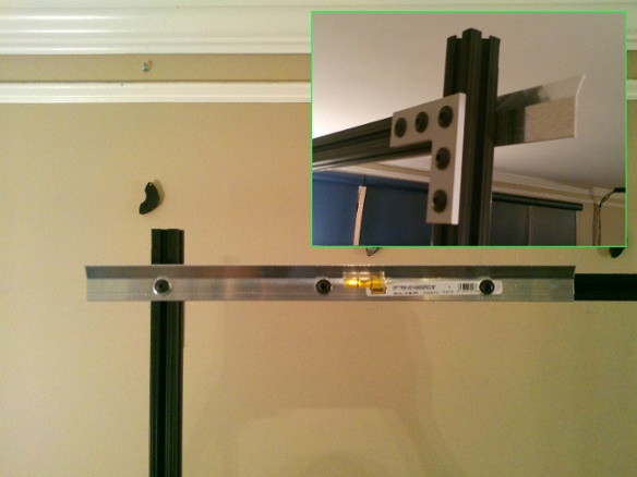
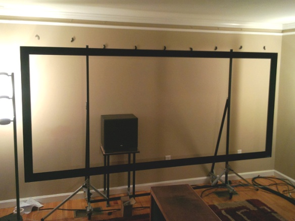
The new screen was mounted on a rolling stand made from 80/20. The screen came with some French cleats for wall-mounting, and by widening the holes a bit I was able to fasten them directly to the 80/20.
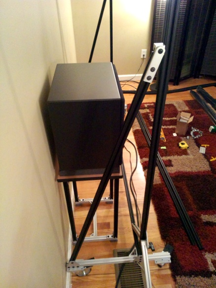
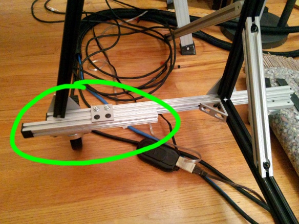
Since the stand was also intended to hold a 12’-wide curtain assembly that cantilevers 3’ out on each side, I included some outriggers for additional stability. They flip up out of the way for moving the stand around.
When I initially set up the new rack I did a preliminary calibration with my 7.1 old speakers, and noticed that my (very) old DefTech sub was sounding a bit warbly and even cut out a few times as I was fiddling with its volume knob. So as yet another upgrade I decided to replace it with an SVS PC12-Plus.
The SVS cylinder has a small enough footprint that it would almost fit behind the screen stand as-is. The old sub location along the wall was already kind of protruding into the walkway and it was only going to get worse when I moved the seats for the larger screen. By adding some little extensions to the stand I got enough depth for the new sub to go up front.
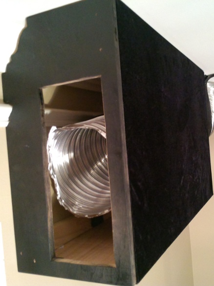
The house was originally built with radiant ceilings and no air conditioning. A previous owner retrofitted a SpacePak system for both heating and cooling, which means there are little high-velocity air ports around the edges of the ceilings. One problem for me was that the living room has them in the corners behind my intended screen wall.
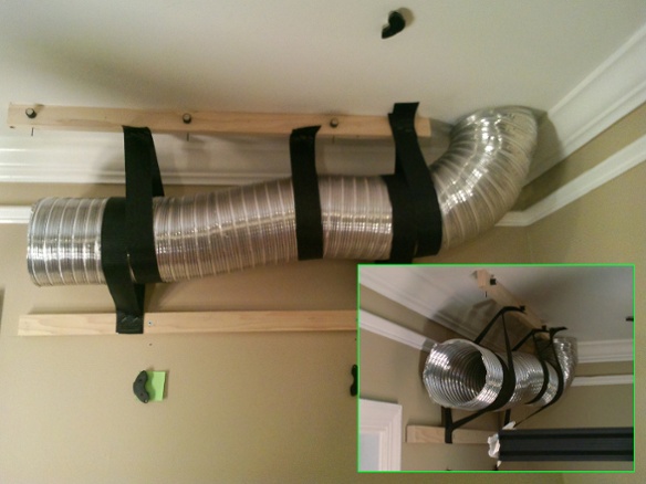
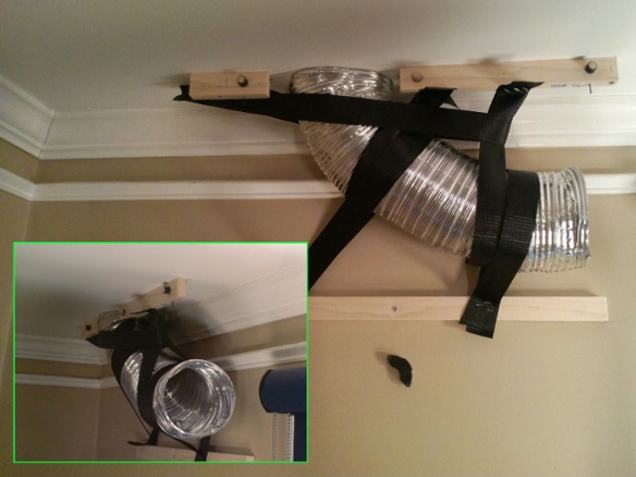
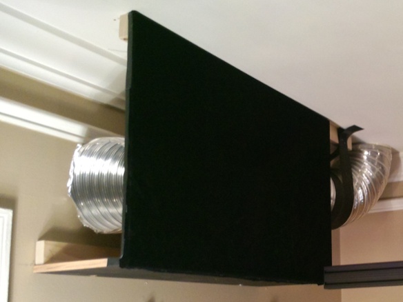
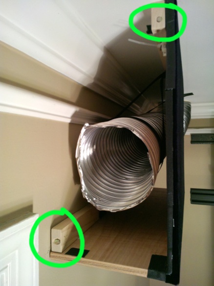
The easiest solution was to build some extension ducts to bring the air out to the room. I attached some 1x2 rails to the nearby joists and studs, and would then mount everything to those.
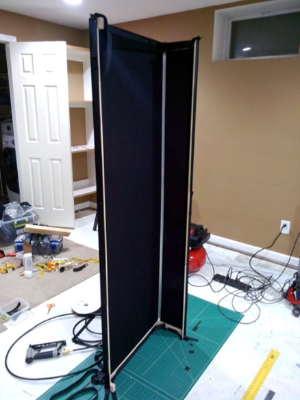
The sides of the extension boxes would be visible in the room, so I knew they’d need to be covered in fabric. In order to make it possible to attach them after the fabric was stapled in place, without cutting any holes, I mounted some dowels in the upper rail that the side walls can can slip onto and hang from.
I strapped some vent tubing to the rails, making sure to keep it within the bounds of the box walls. I was worried about having to figure out some way to attach tubing to the existing ceiling port, but the stuff I ended up using is both adjustable and rigid – basically like a big metal bendy straw – so once bent into shape and strapped firmly in place it kept a pretty tight seal against the ceiling on its own. The tubing is much larger than the high-velocity port so the airflow is pretty much unimpeded. It also ends up feeling much slower at the room end of the tube.
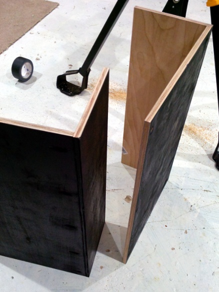
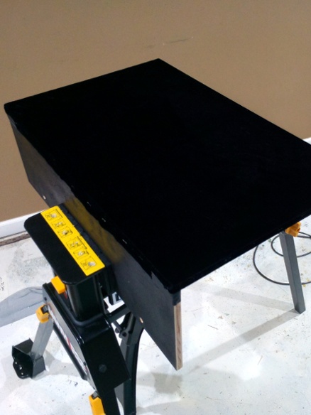
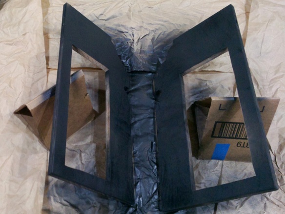
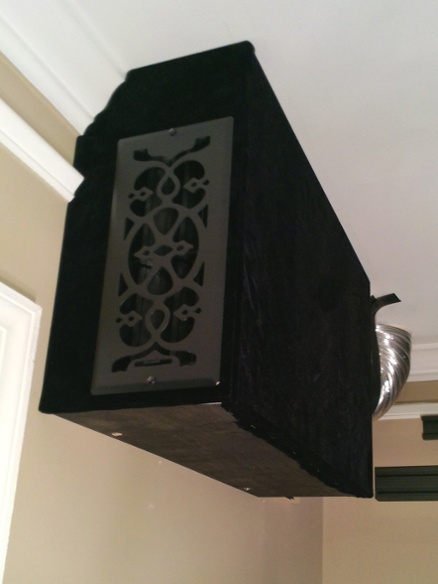
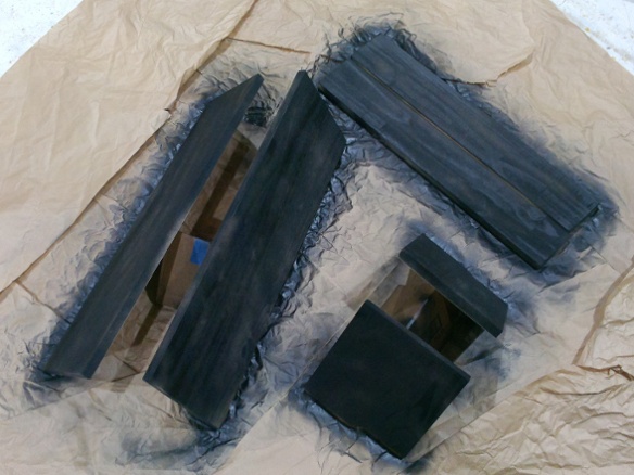
The sides and bottoms of the vent boxes were made from plywood connected with some Kreg-jig pocket holes. All of the plywood would eventually be behind fabric, but I painted it black to ensure nothing would show through even under direct light.
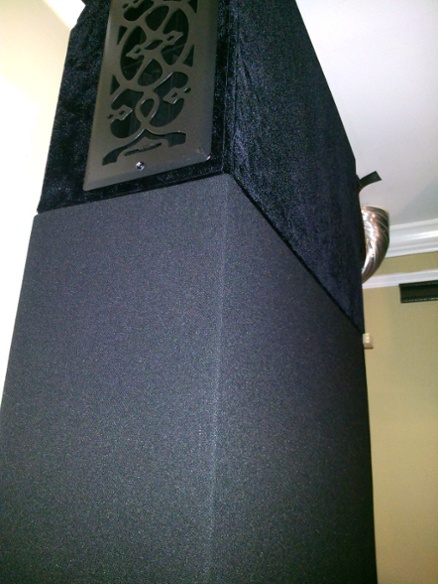
Then I stapled my first piece of Syfabrics triple velvet around the directly exposed side and put the box walls in place. They just slipped onto the top dowels and were fastened to the bottom rail with a couple screws. I also put some cable ties up top to keep them tight against the top rail and ensure they can’t fall off the dowels.
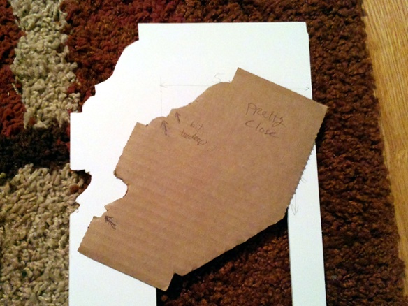
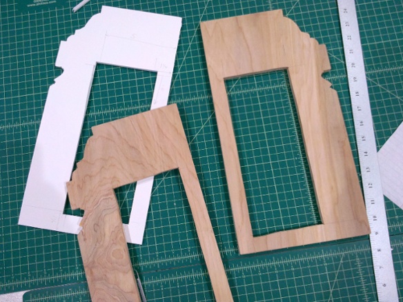
The faceplates had to fit around the existing crown molding. First I tried using a contour gauge with little sliding wires, but the molding is so large and deep that my tool wouldn’t fit. So I just got a piece of cardboard and started trimming it with scissors until it was close, making notes about where I overtrimmed. From that I made a foamcore mockup of the entire faceplate, and then used that as a template for some plywood.
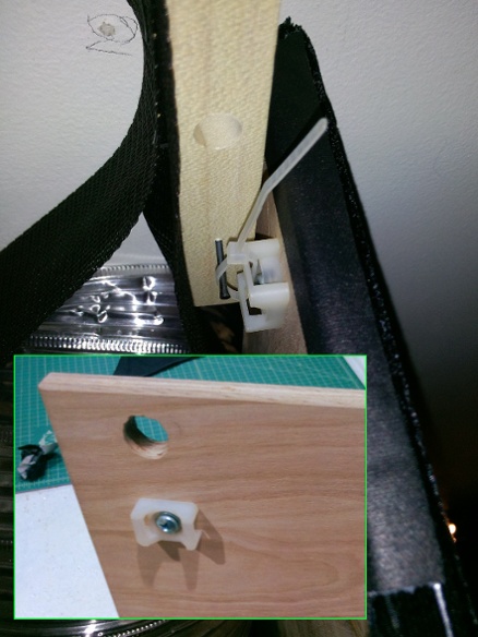
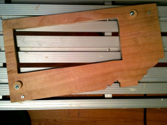
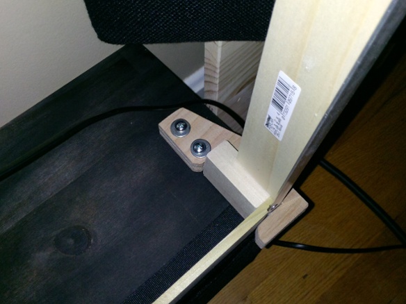
To line up the faceplate I cut some large dowels and mounted them so they would press against the plywood sides. I mounted them off-center so that I could loosen the screw and rotate the dowel to adjust how close it is to the edge. I also embedded some small but strong magnets into the rails and put screws at the corresponding locations in the faceplates. The screws could be turned in and out to adjust the depth. Once everything was lined up and the screws were making contact with the magnets, the faceplate was easily stuck in place and removed by hand as needed.
In this case I glued the magnets into the holes, but even with super glue it was hard to get a really good grip. I also wasn’t crazy about having to put things on hold for 24 hours to get a full cure. It took several attempts to get them glued in there solidly enough that they wouldn’t come out when I removed the faceplate. I used a lot more magnets later on but due to this experience I found other means of mounting them than glue.
Before final assembly I sprayed the velvet with a fireproofing treatment, just to be safe.
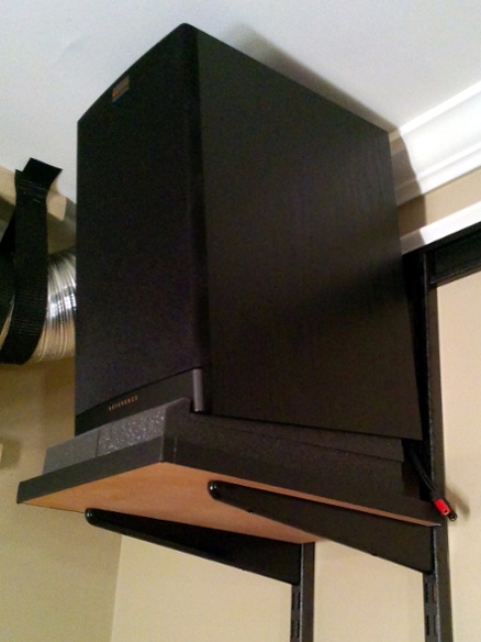
While waiting for parts to dry for the vent extensions, I took care of mounting the height speakers. I used some Klipsch RB-61 II bookshelf speakers and put them on what are basically closet shelving parts. The only actual attachment to the wall is a horizontal hang track at the top. The vertical rails holding the shelf can be adjusted side-to-side in the hang track, and they have felt pads at the bottom where they rest against the wall. The shelf is just MDF with some black gaffer tape on the edge. I used MoPADs to further isolate the speakers and tilt them downward.
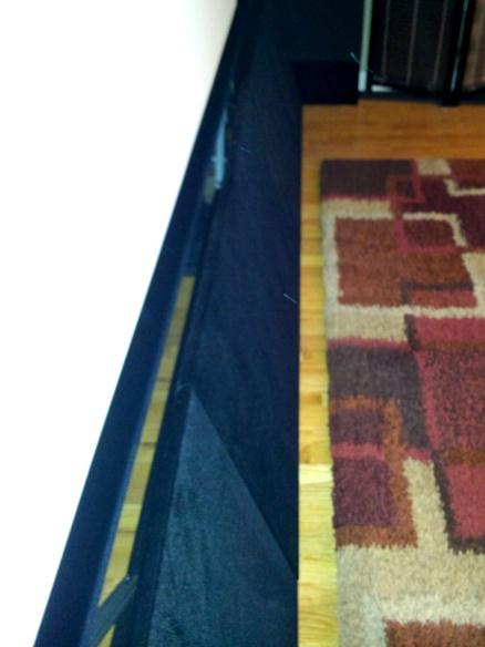
Once the vent boxes were in place, the plan was to put the wide speakers underneath them and then put a frame around the speakers and use some AT fabric to continue the box shape to the floor.
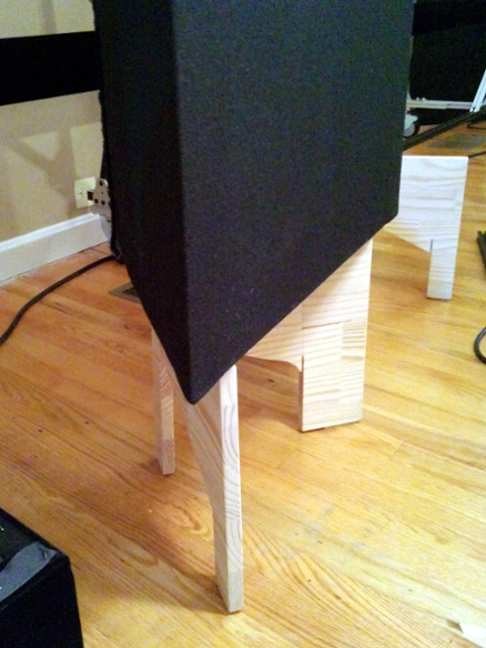
I had a bunch of small aluminum angle that would be perfect for the frame, but it was only 6’ long and the distance from the vent box to the floor was several inches more than that. Then I realized that if I built a simple box that sat in the floor, I could shorten that distance to less than 6’. And I could put my tower speakers on top of the boxes, which would also help because they needed a stand anyway to get the drivers up to ear height.
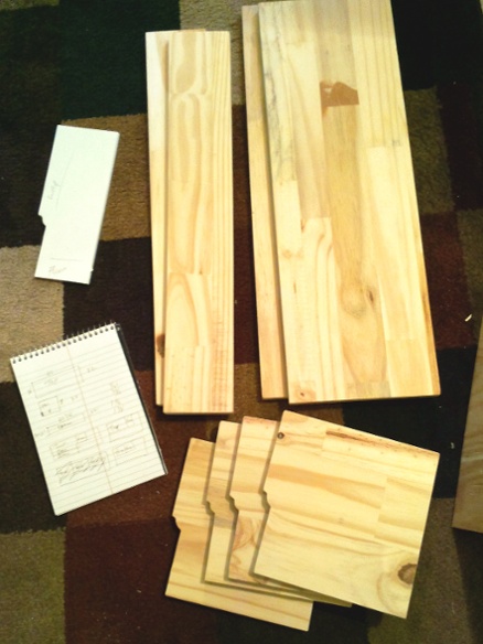
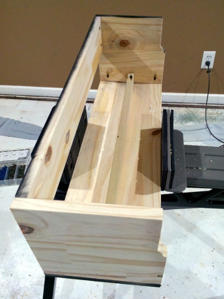
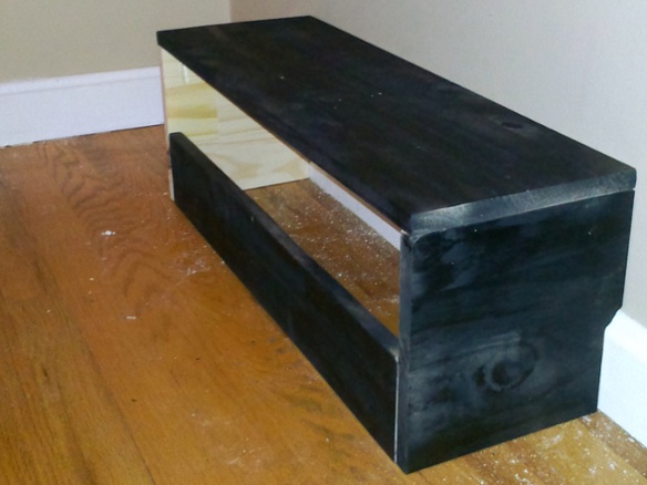
I made a little foamcore template for the molding and then cut the pieces out of a glued panel I had lying around. I painted the exposed surfaces black, hooked everything together with pocket holes, and did a test fitting.
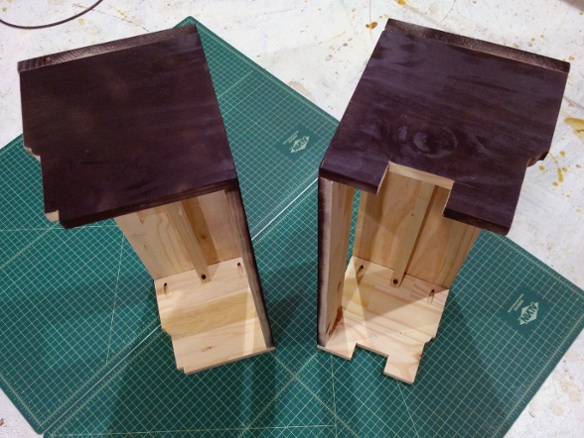
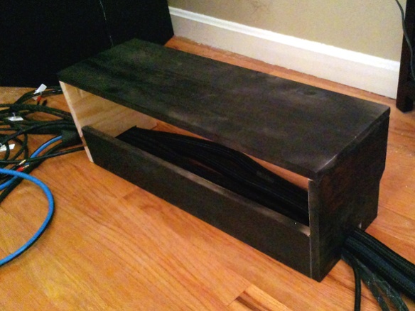
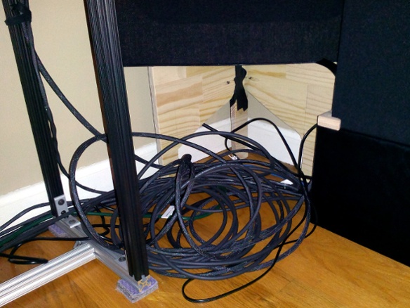
During the test fitting I suddenly realized I’d forgotten to plan for a way to get cables to behind the screen wall. I already had a bunch of cables running along edge of the floor in the old setup, and the new layout would need even more. Having these side stands turned out to be the perfect solution: I cut some channels into the front and back faces so I could run the cables underneath them.
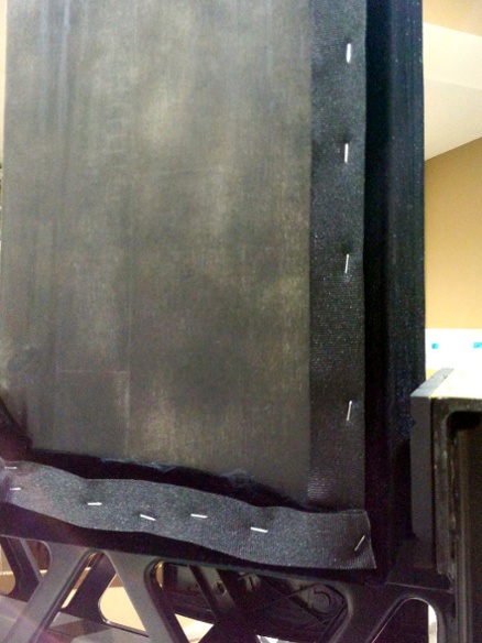
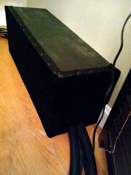
I covered the exposed sides of the stands with velvet and installed them in place. I finally switched to a pneumatic fabric stapler, which definitely made the process easier. I also used some ribbon wherever I put a staple, which ensured that the staples wouldn’t cut the fabric and that they could be removed with less fabric damage if I screwed something up – and yeah I did have to remove a bunch of staples along the way, such as when I accidentally covered the back of one of these stands instead of the front.
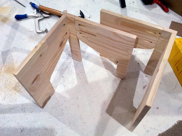
I have some GIK Tri-Traps I’ve been using for years and intended to keep in the front corners, but after setting up the wide speaker stands I realized that there was no longer enough room for the traps to fit if they were sitting on the floor. Lifting them up about a foot would solve the problem.
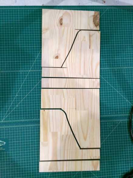
I still had a couple 12”-wide glued panels to work with, so I came up with a simple stand design where I could get all of the pieces out of a single panel with a table saw and jigsaw. Then I just pocket-holed them together. I put felt pads on the bottom to protect the floor, and some non-slip pads on top to make sure the trap doesn’t slide off of them.
They’re not the sturdiest things around but the traps are pretty light so it’s not a problem. One of the joints also split a bit from a pocket hole screw going into an edge, so I had to reinforce it with gaffer tape. If I’d had enough plywood on-hand it would have been a better choice than these panels.
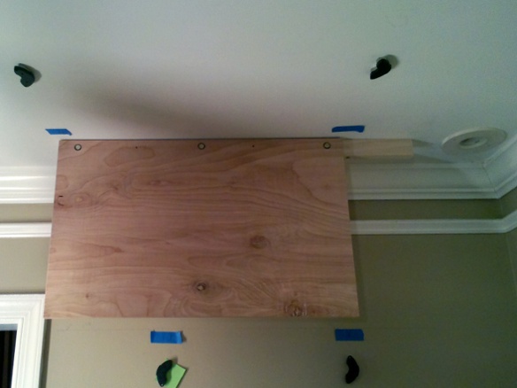
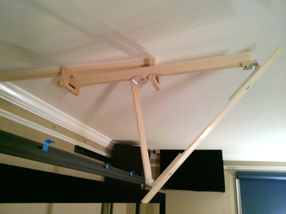
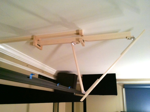
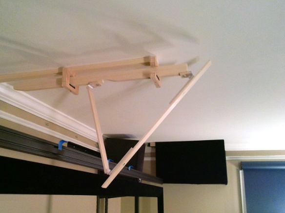
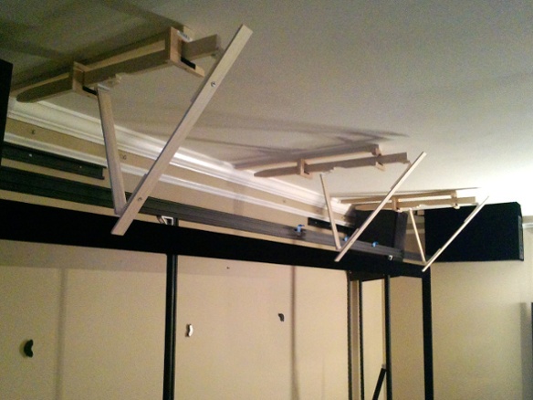
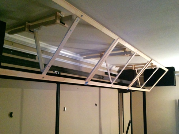
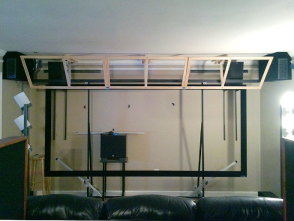
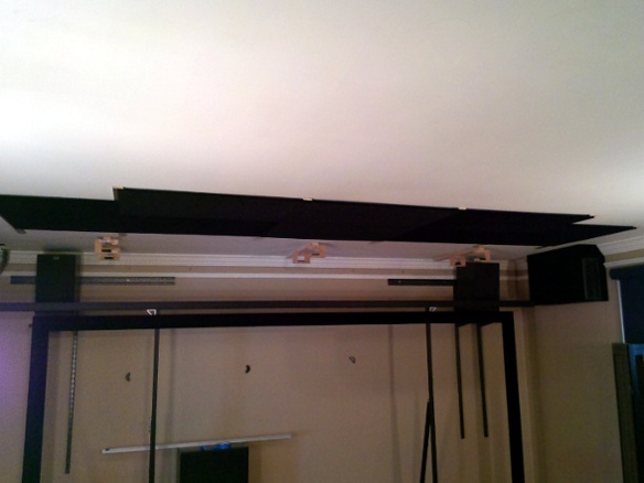
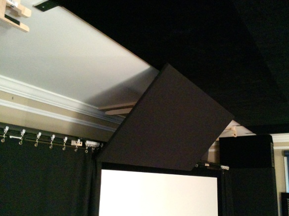
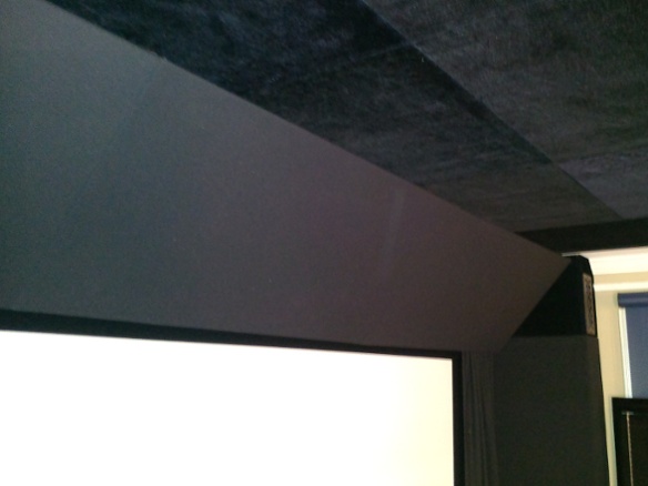
One of the things that took a while was figuring out how to put masking panels above the screen. The mounting requirements were kind of complicated: they needed to touch or be very close to touching the ceiling. They would need to be mounted at an angle. They would need be in front of the screen and curtain, to hide the curtain rail. Since the screen is on a rolling stand they also needed to be easily removed for rolling the stand out. And since some of the measurements for other parts of the screen wall were still uncertain, they needed to be adjustable after the fact.
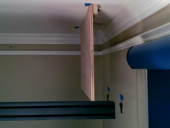
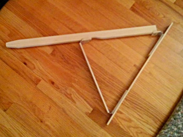
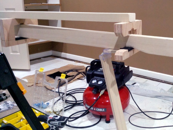
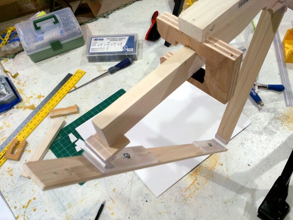
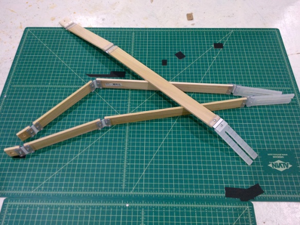
What I eventually came up with was an angled brace that hangs from some ceiling brackets. For adjustability it can slide forward and backward in the brackets and a bit side-to-side. The brace has some adjustable brackets in its own construction which can be used to change the height and angle of the panel.
To remove, you pull the panel away from the wall. Eventually it hits a notch that stops it from going any further, drops it down a bit so it’s no longer against the ceiling, and it can then be slipped to the side to release it from the front bracket. Then just pull away a bit more to get it out of the rear bracket. Installing is just the reverse. It ended up working so well that I’ve demonstrated it for visitors a couple times just for the heck of it.
The ceiling brackets are cut from plywood. I put some felt tape on the bottom to keep things from sliding around or rattling after installation. I mounted them to a 1x2 which is then screwed into a joist.
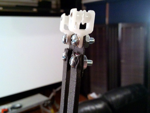
The braces are assembled using some flexible PVC hinges that clamp onto the ends of the wooden pieces. The adjustable components are just polypropylene bars with a long slot cut most of the way down the middle. Before final installation I put little screws through the PVC clamps to lock everything together, and drew some lines on the poly bars to make it easier to get all three braces adjusted the same way.
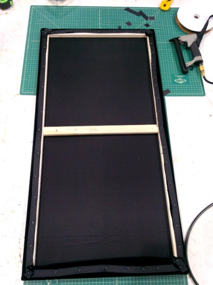
Three braces were installed to hold 24x48 panels made from stretcher bars, which were eventually covered with AT fabric. Together they almost exactly span the distance between the two vent boxes.
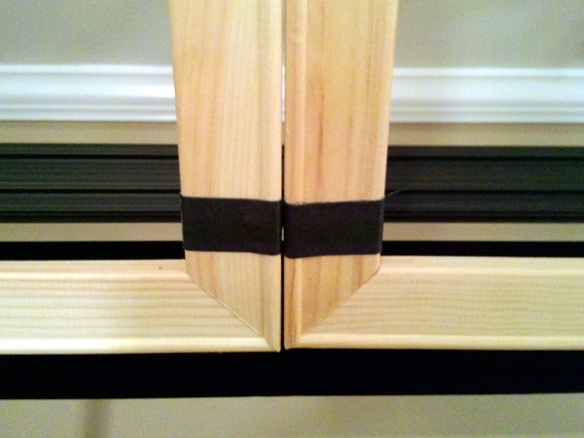
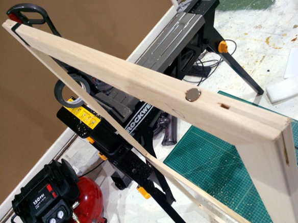
After test-fitting by just taping the panels together, I added magnets to the edges of the frames so that they would stay aligned once they’re installed. I just wrapped some gaffer tape around the frame to hold them in, which was much quicker and easier than trying to glue them. I originally used some small magnets but it became apparent that with tape and fabric between them they didn’t have quite enough hold, so before putting on the fabric I replaced them with larger magnets.
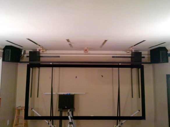
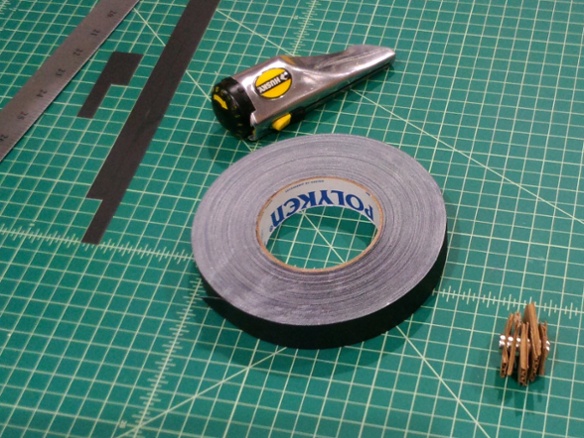
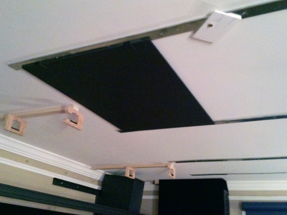
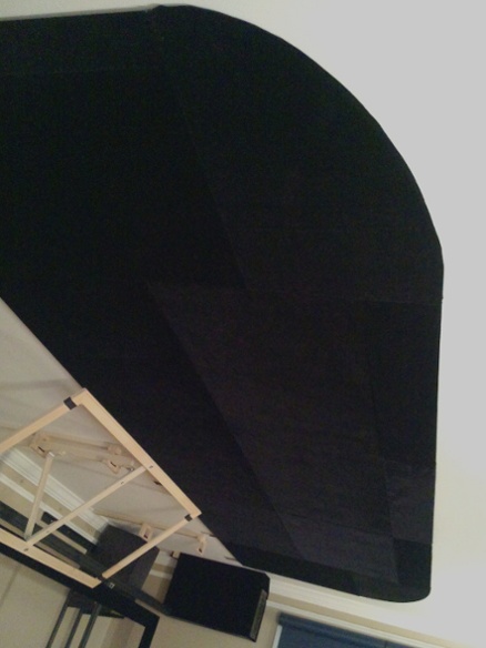
To black out the ceiling in front of the screen, I wanted something that was a bit adjustable and wouldn’t make too much of a mess of the ceiling itself (i.e. no gluing them in place). My idea was to make panels out of foamcore wrapped in velvet to keep them thin and light. To attach them, I’d put some strips of sheet metal along the ceiling and embed magnets in the edges of the panels.
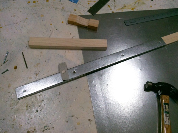
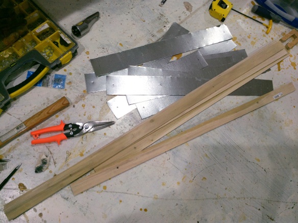
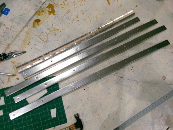
For the metal I just got a sheet of thin duct material. To make it easier to mount the metal and to provide a more rigid surface, I wrapped it around some wooden strips and then screwed the wood into the joists. As it turns out, wrapping the wood ended up giving it a bit of a curve upward, which helped because the joist positions meant that the ends of the rails stuck out pretty far from the nearest joist. The curve kept them tight against the ceiling.
After a quick test, I graphed out a panel layout and installed the full batch of metal-wrapped rails.
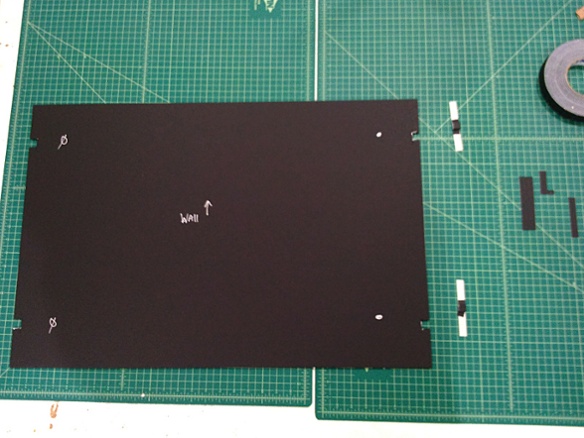
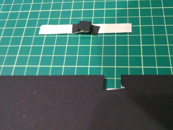
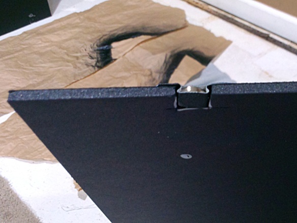
The magnets I used are very strong and almost as thick as the foamcore. To give them a good grip on the sheet metal I just taped them into the foamcore. To avoid the tape pulling away from the foamcore I fastened it to the other side of the panel, so that when the magnet tries to pull away it results in a lateral pull on the tape instead of a lifting action.
One of the things I had to be careful about was to align the poles wherever the magnets from two panels are next to each other on the same rail, so that the magnets don’t repel each other. I used a sharpie to mark a dot on the same pole of each magnet, and then noted the magnet orientation on the panels to make sure I got them installed correctly.
After confirming that these can easily hold a panel in place while still being able to remove it, I built the panels and wrapped them in velvet. I just stapled the velvet into the foamcore with a manual stapler. The staples could be easily pulled out by hand, but held well enough to keep the fabric in place. Once the panels were up on the rails, the pressure against the rail also kept the fabric from moving.
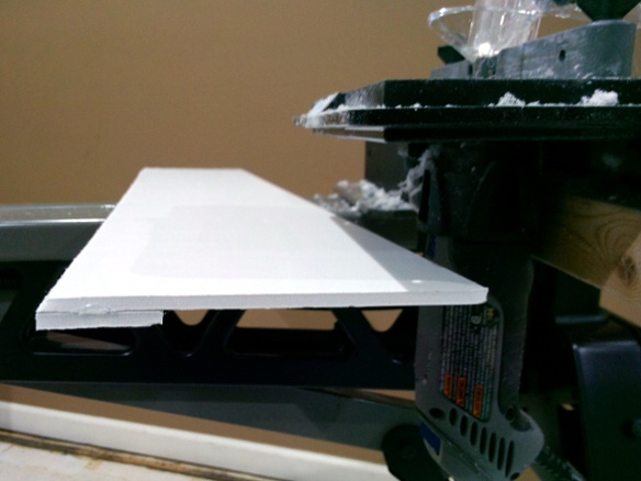
I designed the rail-and-panel layout to have a few inches of rail sticking out past the full-sized panels. I then cut some small edge panels, hot-glued a second layer of foamcore to close the gap to the ceiling and hide the rails, and used a Dremel router to give them a cleaner edge.
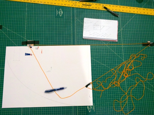
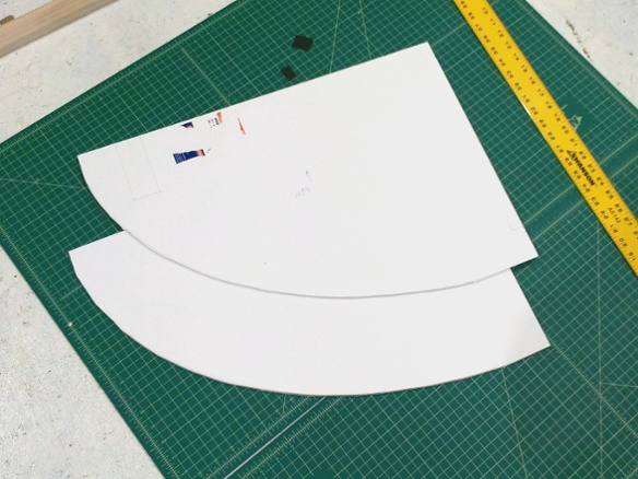
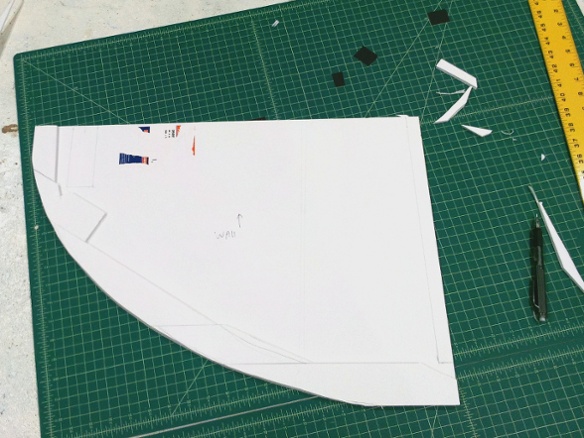
Finally I had two corners to deal with. I decided to curve the corner panels to flow smoothly into the trim panels on the front and side. The simplest curve for that was an ellipse, with the edges of the corner panels as the axes. To trace out the curve I computed the foci positions and taped some tacks to my mat at those spots. I sized a loop of string around the tacks so that it also reached one corner of the panel, and then used the loop and a pencil to sweep the curve to the other corner.
I glued a second layer of foamcore scraps around the edge of the curve, making sure to give enough room to staple to it. Then I routed the curve and put the final panels in place.
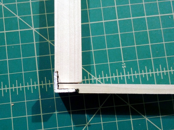
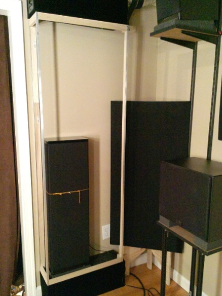
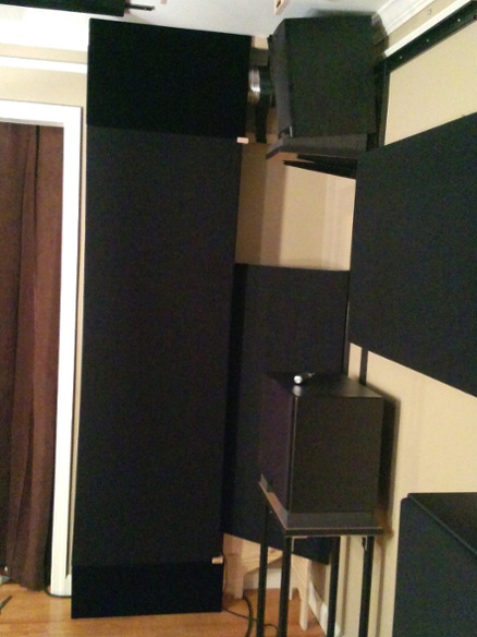
With the wide speaker stands in place I now had less than a 6’ vertical span to fill, so I could use the aluminum angle I had on-hand. I basically needed to make an L-shaped panel to connect the fronts and sides of the vent boxes with the floor boxes. I also needed a wooden edge all the way around as something to staple to. On the visible corner I rabbeted the wood to make the angle flush with the framing.
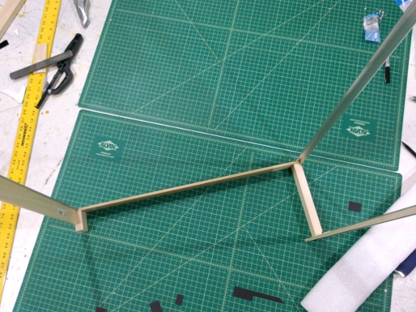
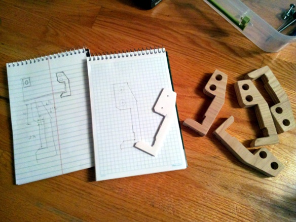
Once I knew that it fit, I had to figure out some way to keep it in place. I also wanted the cover to be easy to remove in order to get to the speaker within. My idea was to have a U-shaped bracket that would receive the back of the frame, and a simple block up front that would trap it against the wall. To install the cover you would just slide it backward. I considered some sort of magnet arrangement to hold it in place once it was pushed back, but in testing I found that the friction-fit was sufficient.
For the rear brackets I did a quick design, then to graph paper, then to a foamcore template, and finally to plywood. I used oversized screw holes to give some adjustability.
Once the frame brackets were ready and aligned, I put the fabric on the frames and installed them. Since there are speakers behind them I used black Mellotone instead of the velvet I’d been using so far. Mellotone does show through a bit, so I covered all of the visible parts of the framing with black gaffer tape first.
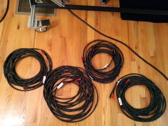
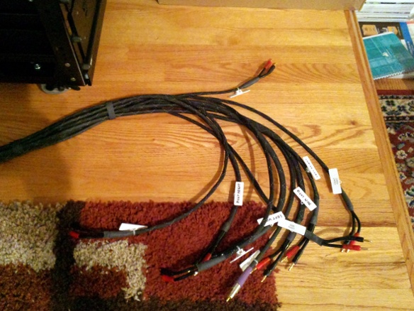
With the side panels in place, it was finally time to run the cabling. This overhaul was adding four more speakers to the front of the room, so I built some 35-40’ cables for them.
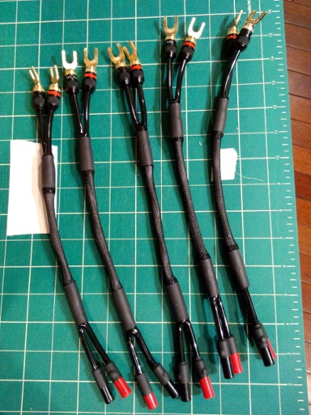
One thing I discovered along the way is that Klipsch’s binding posts don’t accept banana plugs.
[edit: on further reading, apparently they can accept bananas but the holes are plugged out of the box to meet international safety codes or something like that. You can pry a plastic plug out of the end of the post cap to get to the banana port. In my case the adapter cables turned out to be a better solution anyway, as mentioned below]
Since all of my cables are bananas, I made some adapters to go to spades. This turned out to be a really useful thing to have anyway, because with the speakers close to the wall it would have been a huge pain to get to their posts to attach the cables. I installed the adapters well ahead of time, so that after the speakers were in place they each had a little cable hanging next to them with easily-accessible banana jacks on the end.
With all the behind-the-screen cabling in place, I finally installed the screen fabric.
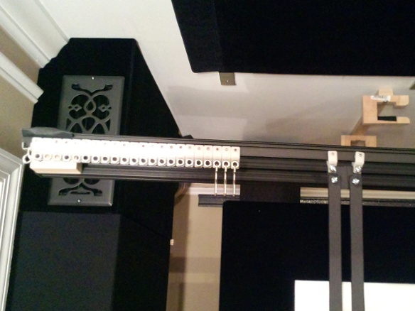
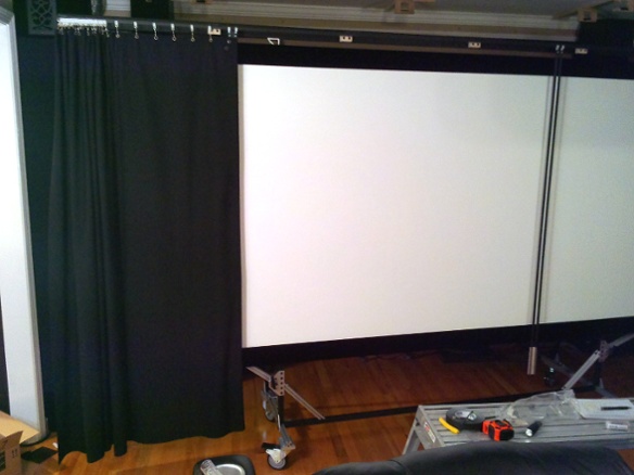
For curtains I used an I-beam design mounted to the top of the screen stand. The carriers have wheels that ride on the outside of the beam. I mainly picked the beam because it can be bent to a tight radius, and I originally thought I’d need to curve it backwards behind the screen to make enough room for the carriers. It also has a variety of mounting brackets available and a very thin final assembly.
There turned out to be enough room for the carriers with the beam mounted flat, so in the end I went with this simpler approach. In hindsight if I’d known that a flat beam would work, I might have used a more traditional system that has a cord and can draw both curtains at once.
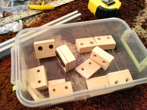
I had already mounted a 12’-long 80/20 rail to the top of the screen stand. Since it would extend unsupported for several feet at each end, I used a double-thick profile that is very rigid. After testing a few types of mounting brackets, I used some shallow ones that would result in the beam being just in front of the screen frame once I added some mounting blocks. The blocks attach to the 80/20 and provide a surface to screw in the brackets at the right depth.
In order to get a clean vertical edge on the masking curtain, I built some edge rails out of small aluminum bars. I attached them to the curtain carriers with a little piece of sheet metal so they hang directly under the beam. I wrapped all of the metal in black gaffer tape.
The curtain needs to be AT, so I used a big piece of Mellotone with some grommets at 3” centers along the top edge. The bulk material was already plenty wide enough to cover the screen vertically so I just cut it to length. It didn’t seem to have any fraying tendencies so I didn’t bother sewing the edges. The bulk material also had a bit of extra-thick weaving on each side, so I just put the grommets into that instead of folding the fabric.
I made the panels over-wide by several inches on each side, so that the ends are folded behind and mounted a second time to a few carriers. This made the edges naturally hang more cleanly and gave about an extra inch of extension beyond the rail, which closed the gaps between the screen assembly and the wide speaker frames.
To hold the curtain tight around the edge rail, I used some very thin and strong magnets with a black epoxy coating. I just wrapped the curtain around the edge and used the magnets to clamp it tight. Four of these magnet pairs on each edge was enough to do the job. The magnets appear as shiny dots in some of the photos but are invisible once the lights are off.
With the curtains in place, the screen stand was done so I pushed it into position and locked the casters.
The I-beam works but the whole thing is very manual. Moving the edges also requires a little finesse, because if you tilt them too much while pushing or pulling the carriers can bind up on the beam.
With the curtains done, I worked on finishing the upper panels. I blacked out the visible surfaces with gaffer tape, covered them with Mellotone, fine-tuned the height and angle, and then put them in place.
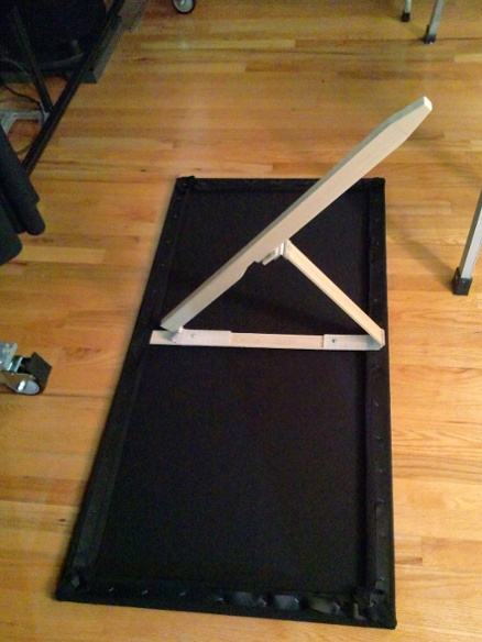
The last major component of the screen wall was the lower masking panels. Like the upper panels, they’re made out of three 24x48 stretcher bar frames. As with the upper panels, I put magnets into the edges of the frames so that when pushed together they self-align and stay together.
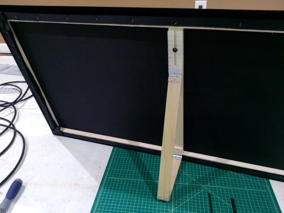
The mounting requirements were that they needed to be touching the floor, angled to cover the stand casters, the angle had to be somewhat adjustable, and the top edge needed to be in front of the curtain. I decided to attach some rear braces similar to a picture frame, and have them just sit free-standing on the floor in front of the screen.
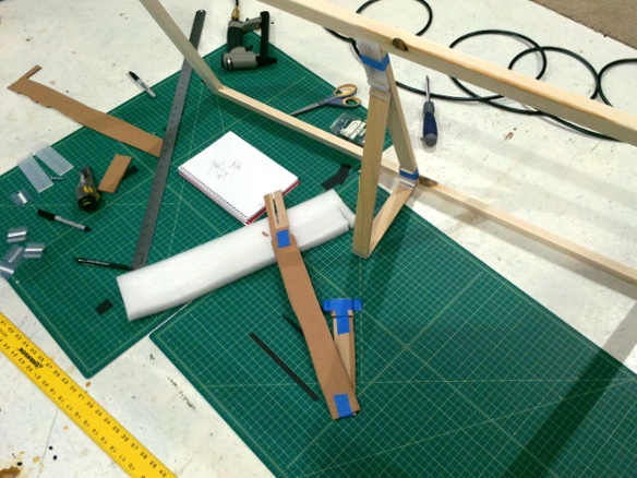
To determine the brace dimensions I first made a quick prototype out of cardboard and tape, used wood and tape to double-check it, and then once I knew the measurements worked I went ahead and built the final braces.
For these panels I used velvet. They needed to be really dark, because when using a 2.35:1 lens setting they will occasionally have picture content projected on them – for example variable-aspect (Tron: Legacy) or just-under-2.35:1 (Lawrence of Arabia) content. For a “correct” presentation of the latter I could also use a manual zoom to the proper height and then draw the curtains to match the width.
With the panels assembled and adjusted, I just dropped them into place in front of the screen and left a little gap for the curtain to fit through. I put some non-skid pads on the bottoms of the braces to make sure they stay where they’re put.
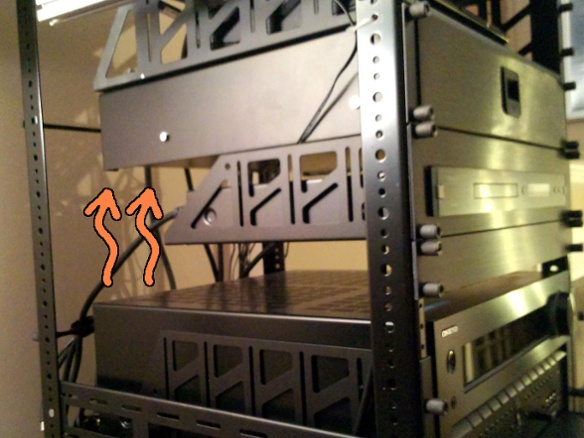
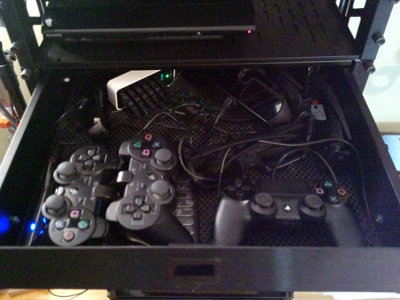
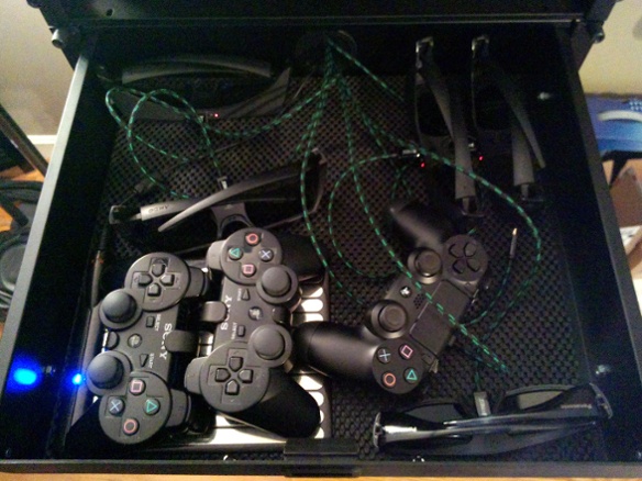
After using the new setup a couple times I noticed that the charging drawer was getting very warm inside. The receiver was a few U below with not much between them, so my guess was that the heat from the top of the receiver was soaking into the bottom of the metal drawer.
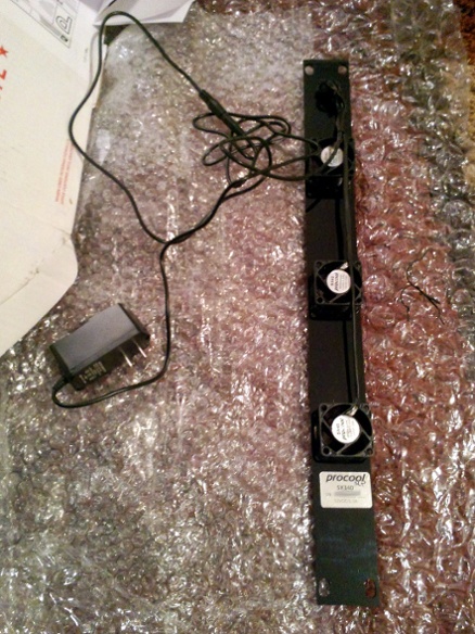
I had already left an extra 1U above the receiver for airflow, so I went looking for a fan panel that could fit there. Most quiet/silent fans seem to be 2U or larger, but I did find a vendor that makes a quiet 1U panel by running with lower airflow. I didn’t need much airflow here anyway.
So far this seems to be working well. The fans are inaudible from the seating, and if I put my hand in the space above the receiver the air there is cool even after hours of operation. The charging drawer no longer gets warm.
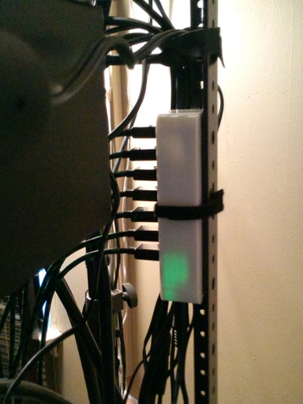
The charging drawer was also a bit cluttered with all of the devices and a USB hub. The charging cables that came with the devices also tended to be stiff and have awkward lengths.
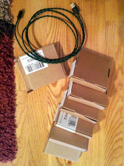
I ordered some 6’-long thin and flexible charging cables, and moved the hub outside the drawer to the back of the rack. This made the inside of the drawer a lot easier to work with.
